

Woodward Peak200 8200-1501 Engine & Generator Control Module
- Product Code: Peak200 8200-1501
- Availability: In Stock
Woodward Peak200 (8200-1501)
Engine & Generator Control Module | Intermediate Technical Document | Revision 1.0 | Date: 2026-02-28
1. Module Overview
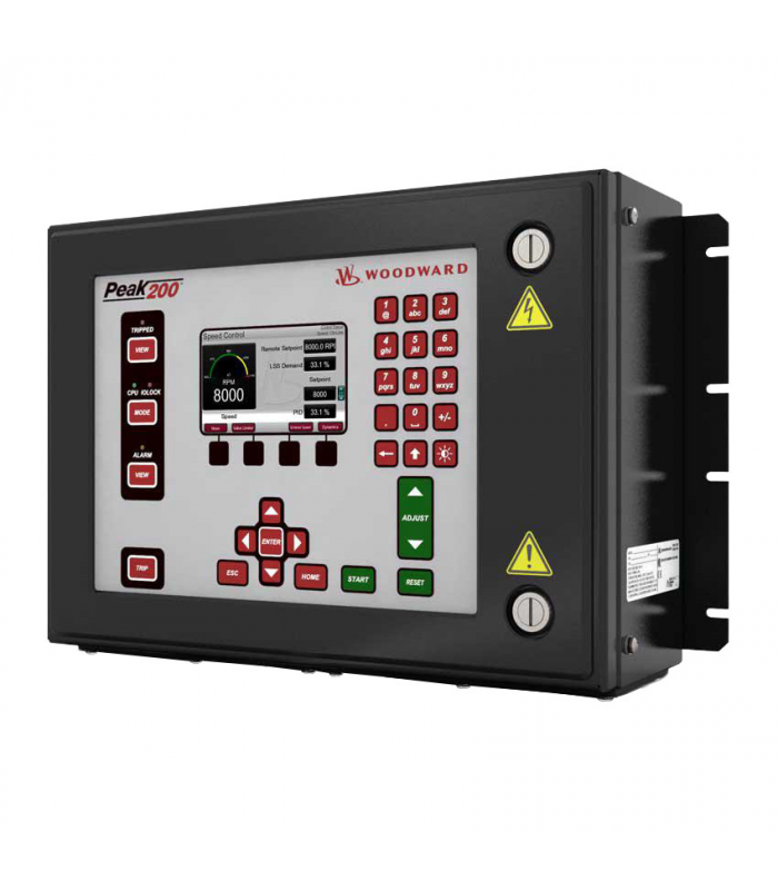
The Woodward Peak200 (8200-1501) is a compact, microprocessor-based control module designed for governing and protecting reciprocating engines, gas turbines, and generator sets in industrial, marine, and power generation applications.
Featuring advanced adaptive control algorithms, the Peak200 8200-1501 provides precise speed regulation, load sharing, and protection functions (over-speed, under-speed, low oil pressure, high coolant temperature) with seamless integration to Woodward's digital control systems.
2. Technical Specifications
Part Number
8200-1501
Control Type
Speed & Load Control (Engine/Generator)
Speed Regulation
±0.25% (isochronous), ±1% (droop mode)
Input Signals
0-5V, 4-20mA, Magnetic Pickup (MPU), Thermocouple
Output Signals
4-20mA, 0-10V, Relay (SPDT), PWM (0-100Hz)
Power Supply
24V DC (18-32V DC), Max Power Consumption 8W
Communication
Modbus RTU (RS485), CANopen, Woodward NET
Operating Temperature
-40°C to +70°C (-40°F to 158°F)
Enclosure Rating
IP65 (Front), IP20 (Rear - Panel Mount)
3. Installation & Configuration
1
Mount the Peak200 module to a metal panel (DIN rail or direct mount) with minimum 10cm clearance for ventilation.
2
Connect MPU (magnetic pickup) to speed input terminals – use shielded cable (twisted pair) to minimize noise.
3
Wire analog inputs (temperature/pressure sensors) and output signals (actuators/valves) to labeled terminal blocks.
4
Apply 24V DC power to terminals (+/-) and verify power LED illuminates (green = normal).
5
Configure speed setpoint, droop, and protection parameters via Woodward PC Configurator software or local keypad.
6
Perform load test and speed regulation calibration; verify protection functions (over-speed trip, alarm outputs).
Important Safety & Operation Notes
- Disconnect all power sources before wiring or servicing the Peak200 module to prevent electrical shock or unintended engine operation.
- Verify MPU gap (0.5-1.0mm) to engine flywheel teeth to ensure accurate speed measurement and prevent over-speed trips.
- Calibrate speed and load control parameters quarterly for critical power generation applications.
- Do not exceed the maximum current rating (2A) for relay outputs to avoid module damage and safety hazards.
- Store configuration backups to a USB drive or Woodward Cloud to enable quick module replacement.
- Inspect wiring connections annually for corrosion (especially in marine environments) and retorque terminal screws (1.2 Nm).